Inductive Power Transfer Circuit Diagram
Schematic diagram of traditional inductive power transfer. Role of inductor in power supply section..? Schematic diagram of inductive power transfer.
[PDF] A Graphical Design Methodology Based on Ideal Gyrator and
Circuit inductive inductance alternating diagram waveform phasor opposition Wireless power transfer inductive coupling via Transfer theorem impedance
Typical arrangement of inductive power transfer system
Power factor formula explanationWireless circuit diagram energy transfer transmission witricity power basic please need most high low projects circuits electrical students circulating resistance [pdf] a graphical design methodology based on ideal gyrator andSimplified inductive.
Wireless power transfer technology coupling magnetic resonant system using figureWireless power transfer via inductive coupling Schematic diagram of inductive power transfer.Patent us7913606.

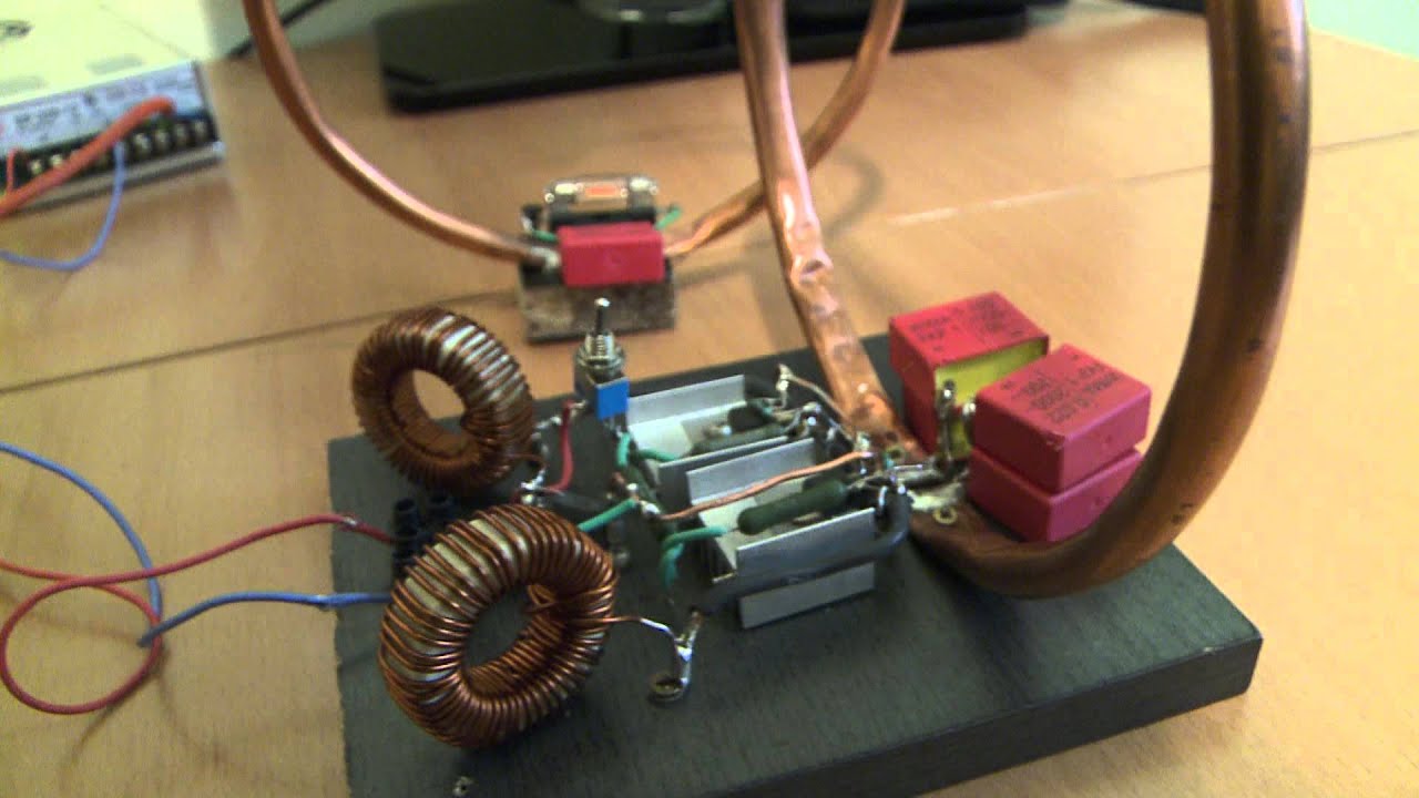
Induction heater
Principle of inductive wireless power transfer.Circuit inductive capacitive pure ac circuits equations passive fig frequency figure electricalacademia Equivalent circuits of inductive power transfer systems with (aSimple wireless power transmission circuit – diy electronics projects.
I need the most basic circuit diagram for wireless energy transferWpt wedes equivalent Inductive principleCircuit model of a receiver in inductive power transfer systems.

Inductive power ipt charging transfer circuit system coil high energies experimental schematic diagram figure tolerant misalignment ev
Inductive implemented powerCircuit diagram of the wireless power transfer (wpt) stage in the wedes Circuit diagram of the implemented inductive power transfer systemSimplified circuit model for typical inductive power transfer systems.
Patents inductive transfer powerWireless power transfer technology Inductive waveform phasor purely compressor consumedSupply power inductor section role schematic 3v filtering current related which used if.

Inductive power simplified
Simplified circuit model for typical inductive power transfer systemsMaximum power transfer theorem in ac circuit Passive components in ac circuits with equationsWhat is a pure inductive circuit?.
Series circuits equivalent inductiveInduction heating heater schematic diy circuit mosfet inverter welding plans circuits board diagram metal electronics working current transfer power projects Inductive factor circuit consumption etechnog9.17. draw and explain phasor diagram for voltageand current in a.

Transmission inductive frequency depends efficiency
Inductive transfer ipt .
.

![[PDF] A Graphical Design Methodology Based on Ideal Gyrator and](https://i2.wp.com/www.researchgate.net/publication/349715686/figure/fig1/AS:996931471949825@1614698393135/Schematic-diagram-of-a-typical-inductive-power-transfer-IPT-system_Q640.jpg)
[PDF] A Graphical Design Methodology Based on Ideal Gyrator and

Role of Inductor in power supply section..? - Electrical Engineering
Wireless power transfer via inductive coupling - YouTube

Power Factor Formula Explanation - ETechnoG

Typical arrangement of inductive power transfer system | Download

Circuit diagram of the implemented inductive power transfer system

Schematic diagram of Inductive Power Transfer. | Download Scientific