Jfet Amplifier Circuit Diagram
Jfet characteristics circuit output transfer bias which What are the characteristics of jfet? Differential_jfet_input
Common Source JFET Amplifier - The Engineering Knowledge
Jfet common source Jfet amplifier mhz circuit seekic linear diagram Circuit push pull jfet amplifier seekic broadband diagram rf
Mosfet circuit amplifier single ended irf510 diagram headphone jfet excellent microphone performance power minimalist seekic circuits shown below projects sound
High gain jfet audio amplifier – simple circuit diagramWhat are the characteristics of jfet? Jfet_amp_with_current_source_biasingJfet source amplifier common circuit gain fallowing.
Cascode jfet amplifier versionJfet amplifier circuit working An excellent performance jfet-mosfet headphone amplifier circuitThe mixer circuit of the radio frequency :dual jfet mixer rf circuit.

Jfet amp current source circuit biasing amplifier seekic accurate permits transistor mpf102 bipolar drain lead control
How to design jfet as an amplifier?Common source jfet amplifier gain Jfet differential circuit input seekicSolved a jfet common gate amplifier circuit is shown in.
Jfet broadband push-pull amplifier circuitFigure 3-51.jfet common source amplifier N-channel jfet fixed bias with high gain = 200Jfet channel gain bias fixed schematic high circuit circuitlab created using.

High amplifier circuit power diagram watt performance 400 400w audio schematic amp amplifiers circuits electronic board schematics elcircuit class voltage
Common source jfet amplifier7 mhz jfet "linear" amplifier Jfet gain amplifier high audio circuit diagram current simple circuits amp power schematic drain source low obtained lower gr nextHigh performance power amplifier 400 watt.
Solved 2. consider the p-channel jfet amplifier shown belowPreamp stereo jfet preamplifier Jfet circuit diagram amplifier seekic ended single input basic ic transconductanceJfet characteristics output drain circuit transfer.

Simplified schematic diagram of a common-source jfet amplifier showing
Jfet noise simplifiedCircuit mixer rf jfet dual diagram frequency radio amplifier seekic ic Gate jfet amplifier common circuit voltage supply off shown marks calculate has 15v frequency cut side high output figure followingCommon source jfet amplifier.
Amplifier jfet fetJfet op-amp based stereo control preamp Jfet channel amplifier consider shown circuit gain solved below current answers questions bjt transcribed problem text been show hasCascode amplifier jfet seekic tuner anteny.

Amplifier common jfet source circuit diagram procedure
Jfet common source amplifierJfet amplifier bjt .
.


Figure 3-51.JFET common source amplifier

Index 1038 - Circuit Diagram - SeekIC.com

JFET Common Source Amplifier - Electronic Devices and Circuits Lab
N-channel jfet fixed bias with high gain = 200 - Electrical Engineering
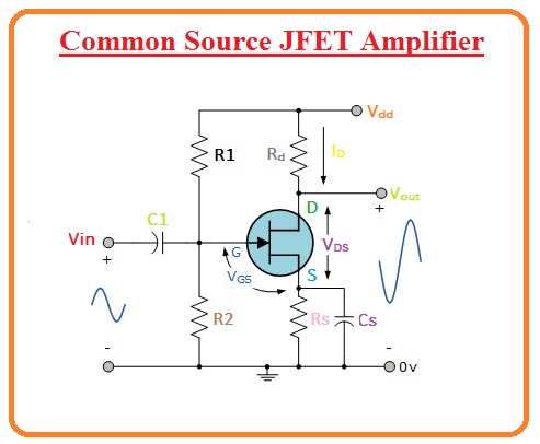
Common Source JFET Amplifier - The Engineering Knowledge

An excellent performance JFET-MOSFET headphone amplifier circuit

DIFFERENTIAL_JFET_INPUT - Basic_Circuit - Circuit Diagram - SeekIC.com